 |
Here's Why Session Amps Are Different
The Power
Amp
 Left:
The power amp stage of a popular British 100W combo. It’s a ‘chip’ output stage
intended for domestic applications. Even though the tiny chip is mounted
directly onto a huge fan assisted heatsink, the chip is said to overheat
after about half an hour of playing at high volumes, which results in a severe drop in loudness or failure.
Left:
The power amp stage of a popular British 100W combo. It’s a ‘chip’ output stage
intended for domestic applications. Even though the tiny chip is mounted
directly onto a huge fan assisted heatsink, the chip is said to overheat
after about half an hour of playing at high volumes, which results in a severe drop in loudness or failure.
The chip is directly soldered to a PCB (the green board), which has no
visible means of support. Therefore, the leads from the chip have to take
the weight of the PCB, the weight of the cables attached to it and the
vibration stresses caused by high playing volumes. Those leads are likely to break off and cause a
failure... not uncommon with chip power amps.
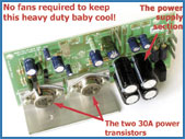 Left:
Session amps employ conventional ‘discreet’ power amp designs employing
heavy duty 30 amp power transistors which will give years of trouble free service. The whole PCB is securely mounted by an ‘L’ shaped ‘heat
transfer’ bracket onto the robust 2mm thick aluminium chassis - which is
seven times better than steel at reducing heat and is more expensive. This bracket ensures that the heat from the transistors is quickly taken away
and dissipated into the chassis. Keeping power transistors cooler will
extend their life dramatically, as heat is the major cause of power amp
breakdowns. Cheap designs allow them to
run hot to save on manufacturing costs and improve profits.
Left:
Session amps employ conventional ‘discreet’ power amp designs employing
heavy duty 30 amp power transistors which will give years of trouble free service. The whole PCB is securely mounted by an ‘L’ shaped ‘heat
transfer’ bracket onto the robust 2mm thick aluminium chassis - which is
seven times better than steel at reducing heat and is more expensive. This bracket ensures that the heat from the transistors is quickly taken away
and dissipated into the chassis. Keeping power transistors cooler will
extend their life dramatically, as heat is the major cause of power amp
breakdowns. Cheap designs allow them to
run hot to save on manufacturing costs and improve profits.
Construction & Materials
 Left:
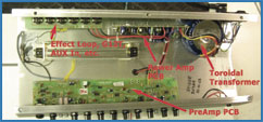
Session amp chassis’ are built using a ‘modular’ format. That means that
there are several PCBs used to enable easy repairs. The ST100R above uses
three circuit boards, each of which can be removed and fault found with
the amp switched on. This greatly reduces amplifier servicing costs in the future.
Left:
Session amp chassis’ are built using a ‘modular’ format. That means that
there are several PCBs used to enable easy repairs. The ST100R above uses
three circuit boards, each of which can be removed and fault found with
the amp switched on. This greatly reduces amplifier servicing costs in the future.
Usually guitar amps are built on one big circuit board. This makes it
virtually impossible to work on the removed pcb whilst the amp is switched
on, and very difficult to remove the circuit board to get at any
components that are faulty. It can turn a quick input socket change into a
1.5 hour job.
 All inter-PCB wiring is hand soldered for reliability. We
do not use connectors anywhere inside our amplifiers. We have found that
the contacts of connectors become corroded or tarnished and affect the
amps long-term performance. Our
amps are used in places where condensation and nicotine are prevalent in
the atmosphere, so these components are deemed in-appropriate for mobile
applications. All inter-PCB wiring is hand soldered for reliability. We
do not use connectors anywhere inside our amplifiers. We have found that
the contacts of connectors become corroded or tarnished and affect the
amps long-term performance. Our
amps are used in places where condensation and nicotine are prevalent in
the atmosphere, so these components are deemed in-appropriate for mobile
applications.
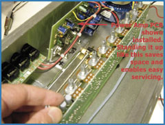 Left:
You can see how the preamp circuit
board has been removed from the chassis and is still wired up so that the
amplifier can be switched on by the service technician, allowing fault
diagnosis whilst running. This Left:
You can see how the preamp circuit
board has been removed from the chassis and is still wired up so that the
amplifier can be switched on by the service technician, allowing fault
diagnosis whilst running. This
saves on time. Components can also be replaced in a jiffy!
Sadly, this style of building amplifiers is bound to make an increase in
production costs, however, we’re sure you’d rather pay a little extra at
the outset knowing that repair costs could be a lot lower when the amp
gets rather elderly.
 Left:
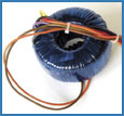
Every amplifier must have a transformer. Left:
Every amplifier must have a transformer.
The type we use are known as ‘toroidal’. They are recognised by the
circular doughnut shape. Unlike conventional ‘laminated’ transformers,
these radiate hum in all directions around it’s 360° arc. This causes most
of the electromagnetic 50Hz hum radiations to self cancel - reducing the
hum picked up by your single coil pickup equipped guitar by as much a 70%.
No amount of cavity screening in your guitar can stop electromagnetic radiation from entering the guitar’s signals... so, toroidal transformers dramatically reduce the cause in the first place.
These transformers are naturally more expensive - but worth every penny.
|
 |